![[Front view of the radio set]](images/radio1.jpg)
Front view of the radio set.
Front view of the radio set.
Just about everyone who is into electronics will have built a radio receiver at some stage. However, although I had experimented with building some communications equipment previously, until recently I had not built a functioning broadcast band receiver.
At a very early age, I had tried building the ZN414 based receiver from Dick Smith's "Fun way Into Electronics", but I was not able to get it to go. In any case, this circuit was for the AM band, and while this was a reasonable choice when it was designed in the late '70s, by the 1990s, most stations of interest were on the VHF FM band. (It is interesting to note that the "Funway" kits were still on sale until at least 2010, by which time some of the designs were quite dated.)
Having grown up in the solid state era, I also had no practical experience with equipment using thermionic valves. I thought it would be interesting to at least build up an experimental circuit using a valve, and gain some familiarity with the old technology. I had acquired a solitary 6AV6 from Oatley Electronics some time ago for this purpose, but it sat around for quite a few years before I got round to trying to do anything with it.
One day, I came across the valve while sorting through some junk, and decided to try and build something with it. I found some contacts from a connector that would fit the pins, and soon had an audio amplifier wired up using jumper leads. I used a 240V:16V mains transformer for the output transformer.
This valve is quite unsuited to use as an audio output stage, however, on connecting a signal generator to the amplifier, I was able to hear a faint tone in the loudspeaker. The low output was no doubt partly due to the low plate supply voltage - I was using a couple of lab power supplies in series, to give about 60V. Calculating the output power gave a figure of only a few milliwatts. However, it was still a functioning amplifier.
![[Valve amplifier wired up with jumper leads]](images/valveamp.jpg)
Valve amplifier wired up with jumper leads.
This experiment satisfied my immediate curiosity about valve technology. However, I then thought of my failed attempt at building a radio. Perhaps I could have another go at building one? And perhaps a valve-based design would be practical? This would make another interesting experiment, and would result in something with practical utility. (I am not really a believer in the purported sonic benefits of valve amplification, so I couldn't see the point of going to the trouble of building up a valve stereo amp. However, a radio would be a useful application of the old technology, even if the quality of sound reproduction was not optimum.)
One problem still apparently remained. To produce a radio that I would want to listen to, it would need to be capable of receiving FM stations. And, in Australia at least, valve FM radios are virtually unheard of, as FM broadcasting only commenced here in the late 1970s, by which time valves were almost completely obsolete. Fortunately, this deficiency was only due to lack of demand, rather than any intrinsic limitation of valve technology.
I recalled reading Cool386's accounts of constructing "Fremodyne" receivers (essentially a superheterodyne receiver, with a superregenerative slope detector.), and decided to give one of these circuits a go. Fortunately, I had a copy of the March 1967 issue of "Electronics Australia", which describes this circuit.
The next task was to acquire some suitable valves to experiment with. Although I had a basic understanding of the different types - triodes, tetrodes, pentodes, etc, I had no idea of any specifics. I did not know which types were fairly common, which ones were most suitable for RF or audio output applications, what was available in terms of multi-element packages, or what the pinouts were. (Imagine going shopping for transistors, without knowing that a BC548 or 2N2222 is probably a good choice if you don't know any better!)
The EA circuit specified a 12AT7 twin triode for the RF stages, 6AU6 and 6AQ5 pentodes for the audio amplifier, and a 6X4 rectifier. However, it was clear that I might have to make substitutions to suit parts that I could actually get hold of. A bench power supply (or three) could initially be used for the HT supply, and I could always use a silicon diode in place of the rectifier valve. The audio stage could also be replaced by an external amplifier for testing, and in any case, would probably not be very critical. This left sourcing an RF valve as the main priority.
I saw there was a small selection of valves available on ebay. But these were all marketed as "audiophile" quality, together with "audiophile" prices, that I was not prepared to pay! I also saw that RS Components still stock a small range of valves, although unfortunately not any 12AT7s. I ended up ordering a 12AX7 from them, which is at least pin-for-pin compatible with the 12AT7, even if not equivalent in performance. I figured that I might be able to use it for the audio stage if it turned out to be no use at RF.
I also ordered a few 9-pin sockets from RS - again, not knowing much about the different types of valve bases, I had to hope that these would be suitable for all the valves I wanted to experiment with. These parts were quire reasonably priced, although when it arrived, even I could see that the quality of construction of the Chinese-made valve was not particularly high.
One other possible source of valves suggested itself - a couple of old and nonfunctional RF signal generators that had been sitting in my shed for some years. While I didn't really want to pull these things apart, they weren't any use to me in their current state, and I figured that if I "borrowed" some valves from these, it would at least be easy to restore them at a later date if desired.
One instrument was fitted entirely with large 8-pin valves, which I rejected in the hope that I could eventually build up my radio in a fairly compact cabinet. However, the second one yielded two 12AU7 twin triodes, and two 6CK6 pentodes, all in miniature 9-pin packages. I thought a 12AU7 would be worth a try for the RF stages, especially as Cool386 suggests this as a possible substitute in one of his other designs. (Fortunately, pinout and ratings information is quite readily available these days - as with semiconductors, a quick Google of the part number and "datasheet" provides all the necessary data.)
When working with RF circuitry, the physical layout of the components can be quite critical. I didn't want to go to the trouble of fully building up the radio in a cabinet, only to discover that it wouldn't work due to bad layout. And while it would be possible to build the circuit up on a breadboard (using a socket for the valve), this also be quite inappropriate for a VHF circuit. Therefore, I decided to prototype the circuit using point-to-point construction and tag strips on an aluminium panel, to provide some shielding.
![[Experimental radio circuit built on metal plate.]](images/radio2.jpg)
Experimental radio circuit built on metal plate.
I started off experimenting with the "Fremodyne" circuit. There were a number of uncertainties that I faced when building it up. I had some nice dual-gang tuning capacitors with reduction drives that I wanted to use, but they were not the value specified on the circuit. The details of the transformer for the superregenerative detector were not particularly clear either - I had a few IF transformer cans from the valve era, but the characteristics of the core were unknown.
I built up the RF stages of the EA circuit, and managed to get the VHF local oscillator to go, but the 27MHz detector stage could not be made to operate. I tried experimenting with a number of modifications, including changing the phasing and number of turns on the transformer, but it still refused to work. I eventually decided that either the transformer core was unsuitable, or that the 12AU7 was a poor choice of valve.
However, given that the VHF stage seemed to work OK, I though it might be possible to give one of Cool386's VHF superregenerative designs a go. I therefore built up the detector stage from the "Simple 12AT7 VHF FM Tuner". On powering up the circuit, the VHF signal could clearly be seen on an oscilloscope, even just using the probe shorted to the earth lead as an inductive pickup. Winding back the timebase showed a clear quench waveform envelope.
I then connected up the circuit to an old stereo amplifier, which gave plenty of noise from the superregenerative detector. After some very careful adjustment, I could just make out a signal amongst the noise. It wasn't much, but it was a working radio receiver, finally!
However, there were still a number of problems to solve. Firstly, the signal-to-noise ratio was really not good enough for everyday listening. This was probably due to insufficient signal strength - an antenna was not connected for the initial experiment. I connected a length of wire to the oscillator coil via a 1pF capacitor, which gave a considerable increase in signal strength, provided the antenna was adjusted correctly. But even with this light coupling, moving the antenna would pull the receiver out of tune, and could even cause the oscillator to drop out completely.
I therefore built up the grounded grid RF stage, which eventually gave a good improvement in stability, though it took a bit of fiddling to get it operating correctly. Another problem was that the oscillation would drop out at the top end of the FM band, right where my favourite station was! After quite a bit of experimentation, I realised this was happening because I had left off the 1nF bypass capacitor on the plate of the detector valve. I had thought this was only for filtering the quench waveform, which I wasn't too worried about initially. But it actually functions as an RF bypass, and if it is missing, the plate and the audio output will be "hot" with RF! I think the cable running to the audio amplifier may have been forming a quarter wave stub at about 108MHz, causing the oscillation to drop out. Fitting the capacitor cured the problem.
It was then possible to sit back and listen for a while, and evaluate the performance of the radio. Performance was a bit variable - sometimes the signal was good, but sometimes it would fade away into noise over the course of an hour or so. I eventually found this was due to a source of interference somewhere near my workbench - I didn't work out exactly what it was, but I would guess that it was one of the many switchmode supplies I have, and its harmonics were slowly drifting on to the station of interest. Even an ordinary transistor radio was affected to some degree, but a slope detector is obviously much more vulnerable to this type of interference, as it will respond to both AM and FM.
At this point, the receiver was quite pleasant to listen to, provided that a noise-free signal of sufficient strength was available. But there were still a few other things to do before I could commit to build up the radio properly. One remaining problem was with the tuning. The circuit requires a tuning capacitor with a maximum capacitance of around 20pF, but the tuning gang I had was about 320pF when fully meshed. I had initially overcome this problem by padding the tuning control with a series 22pF capacitor, but this makes the mapping of control rotation to station frequency highly nonlinear - the tuning is very touchy at the high end of the band, but stations are quite spread out at the low end.
One way around this is to change the L/C ratio of the resonant circuit, and use a lower value inductor in order to permit the capacitance to be increased. I tried this approach, but the impedance of the circuit was disturbed to such an extent that the oscillator would not run at all.
However, I realised that another approach was possible. If the tuning capacitor is connected to a tapping part way up the oscillator coil, the coil will function as an autotransformer, and transform the impedance of the capacitor to a higher value at the top of the tuned circuit. Since capacitance is inversely proportional to impedance, this is the same as transforming the capacitor itself to a lower value - exactly what was needed!
It took a bit of trial-and-error adjustment of the tapping position and the padding capacitors to get the tuning range aligned with the limits of the FM broadcast band, but eventually an acceptable result was achieved. While it is still not completely linear, the tuning at the top end of the band is now a lot less touchy.
After further listening, I realised that, while the sound quality was fairly good, there was some intermodulation distortion present during loud passages. I thought this might be due to the Q of the tuned circuit being excessive, and the linear portion of the slope detector's frequency/voltage curve being smaller than the maximum deviation of the FM signal. I therefore decided to increase the bandwidth of the tuned circuit by placing a resistor in parallel. It was necessary to be careful not to overdo this, or the oscillation would stop completely, and I eventually settled on a value of 10k. The resistor seemed to make a small improvement, although I didn't have the instruments necessary to verify this in an objective manner. (The resistor also changed the tuning range slightly, so it was necessary to go back and tweak this again.)
The next job was the audio amplifier stage. While I did not need a huge amount of power, at least a couple of hundred milliwatts would be required. It was also necessary to think a bit about the power supply at this point, since the available output power will strongly depend on the plate supply voltage. I decided that it would be good to have the option of running the radio from batteries, for portable us. While this does not really make sense when using indirectly heated valves, it is not completely impractical, and I had some 6V SLA batteries that would do for the heater supply. The 'B' battery could be made up of a string of 9V batteries, and a practical voltage would be in the range of 60-80V (Commercial battery valve radios often used a nominal figure of 67.5V). Therefore, the audio amplifier would need to have acceptable performance with a supply voltage in this range.
It was clear that the 6AV6 circuit that I had tried previously would not be up to the task. So, I started off using one of the 6CK6s that I had salvaged from the signal generator. With a plate supply of 85V, and driving the valve with an audio oscillator, I managed to achieve about 150mW into an 8 ohm speaker, using the 5.5V tap on a 2155 mains transformer for output coupling. (Note: power was calculated using the nominal impedance of the speaker, and may be inaccurate). This was actually quite loud. But, on connecting the amplifier and detector stages together, the results were somewhat disappointing. It appeared that the superregenerative detector could not drive the amplifier to full power, and that an additional stage of amplification would be required.
I could have built up another stage using half of one of the 12AX7 or 12AU7s. However this would have resulted in extra heater current drain - a problem for battery operation, especially given that the 6CK6 already drew around 700mA. I therefore decided to see if I could find a single valve that could provide both gain and output stages.
Looking through numerous audio amplifier circuits in old copies of "Electronics Australia" revealed a couple of possibilities: the 6DX8 and 6BM8. Both of these are combination triode/output pentodes, and each had a combined heater current of about the same value as the 6CK6 by itself. It was then necessary to source some of these devices. The project was put on hold for a couple of weeks until the local radio swap meet was on, and then I was able to pick up a couple of 6BM8s, and also some 12AT7s to try in the RF stage, all at quite reasonable prices.
I was then able to build up an audio amplifier stage using the new valve. The circuit was derived by taking a bit of an average of all the designs I had seen in EA - though they were all pretty similar anyway. The increased gain allows the use of negative feedback, which will hopefully result in less distortion. I also found a 100V line PA transformer to use for the speaker. Performance was quite good, and after calculating some suitable values for the coupling capacitors (I had initially used values chosen essentially at random, in the interests of getting the thing up and running quickly!) a finalised copy of the circuit could be drawn.
![[Circuit diagram.]](images/circuit.png)
Circuit diagram.
With the circuit done, attention could now be given to the mechanical layout and case. I had initially thought that I might design a PCB, possibly using surface mount passive components, for an interesting contrast between the old and the new. However, after seeing how critical the layout of the circuit could be, I decided that this was too risky, and reverted to conventional point-to-point wiring using tagstrips.
I had a suitable folded aluminium case, with a "hammertone" paint finish that was still in quite good condition. It would only require a front panel to be fabricated. I decided to attach all of the internal components to the front panel, so that it could be removed from the box without disconnecting anything. The 6V lead acid 'A' battery would fit along one side of the case, though I had to grind away the rivets that held the case together to get enough clearance.
As the battery, and also the speaker that I had chosen, was quite a tight fit, I decided to make a CAD model before putting everything together, to check that it would all fit. This was necessary, as the battery would be held in the case, while the speaker would be attached to the front panel, and it would not be possible to see the amount of clearance until the front panel was screwed down. I also made sure to check that there was enough room for the tuning capacitor to open fully. However, it looked like I would be short of space for the stack of 9V batteries I had intended to use for the 'B' supply, so I decided to look at other options for the power supply.
I would have liked to provide some sort of dial scale with frequency markings, as a tuning aid. However, with the speaker fitted to the front panel, there was not enough room left for the scale. The tuning control only has about three full turns, so this is fortunately not too much of a problem.
The front panel was made from 3mm aluminium plate. This was given a scratch finish with sandpaper - an easy way to give a presentable finish. I fitted some aluminium rivets to the front flanges of the box, and drilled and tapped these to accept M4 screws for holding the front panel. Although purpose-made nut inserts can be bought for this task, the rivets worked quite acceptably.
The speaker was then fitted to the panel, using some salvaged fabric from a discarded armchair cushion for the grille cloth. I then made up an aluminium bracket that would attach to the back of the speaker, and would hold the valves and other circuitry. In this way, when the front panel was removed, all of the components (excepting the battery) would come away with it, allowing easy access.
After fitting the valve sockets, controls, speaker transformer, and some tagstrips, work could commence on wiring up the circuit. It was necessary to have a look at the circuit diagram and work out which nodes could be connected using a terminal of one of the mechanically anchored components, and which would require a tagstrip terminal to connect two or more leaded components together.
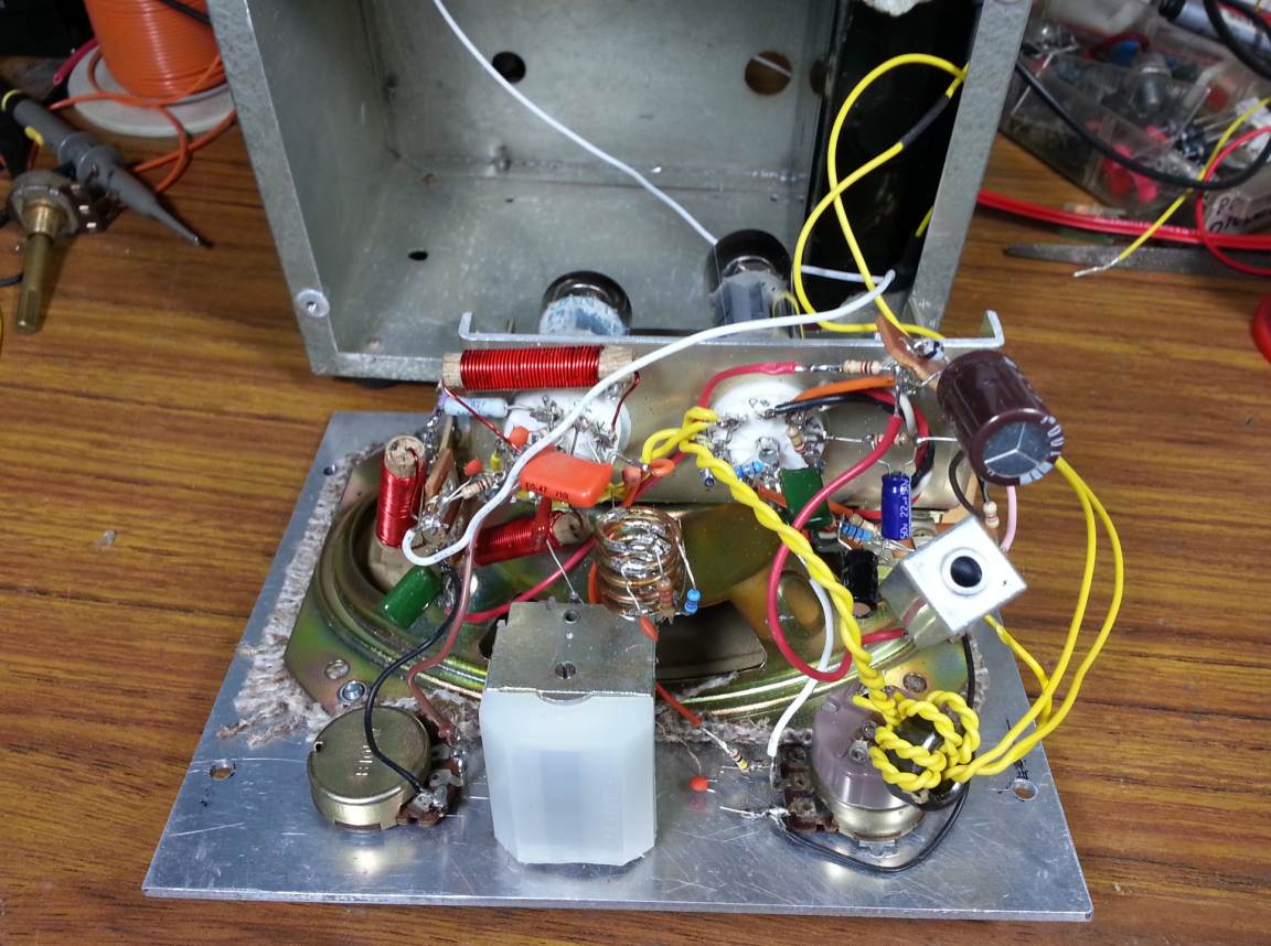
Bottom view of circuitry, showing point-to-point wiring.
I had intended to use 1W resistors for the circuit, as although such a high power rating is not necessary, the larger components have thicker leads, and would be more rigidly held when assembled point-to-point. However, my resistor order got lost in the mail, and I got impatient and decided to use standard 0.25W resistors, which I already had in stock.
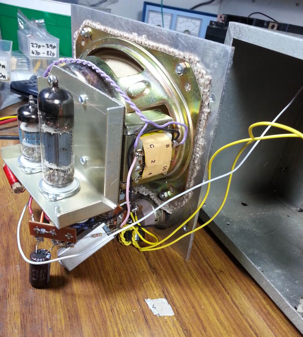
Side view of circuitry, showing valves and speaker transformer.
After assembling the circuit, it was tested, and found to work just as well as the prototype. All that remained to do was to sort out something for the power supply. My original idea of a stack of 9V batteries was probably not a very good option, as the AF amplifier needed about 10mA to give best performance, so the batteries would need frequent replacement if the radio was used regularly. Therefore, I abandoned this idea, and as an interim measure, I cheated and made a one transistor voltage step up circuit using a BC639 and an unidentified transformer out of my junk box.
This converted the 6V battery voltage up to around 70V, which was sufficient to run the rest of the circuit. There was initially a bit of a problem with the switching frequency beating with the superregenerative quench frequency and causing whistles in the speaker, but enclosing the voltage converter in a metal IF transformer shield can fixed this. Total current consumption, including the valve heaters, was about 1.1A at 6V, which should give a runtime of several hours from the 10Ah gel cell.
![[Circuit of power supply.]](images/psu_circuit.png)
Circuit of power supply.
For mains operation and battery charging, I could have fitted a power transformer inside the case of the radio - there was room for a 2155 transformer, which could have been partially rewound to give voltages for both the 'A' and 'B' supplies. However, this would have meant either an inconvenient captive power cable, or an IEC inlet, which was not really in keeping with the "vintage" theme. (And, a regulated float charger would have required more of those new-fangled semiconductors...). I therefore decided to provide a small socket for an external battery eliminator, which would provide a regulated 6.9V supply.
It was necessary to use a short, thick cable for the power supply to avoid voltage drop that would prevent the battery from charging fully when the radio was on. However, this stiff regulation was a bit of a liability for the valves, as their 6.3V heaters would be overrun somewhat. To counter this, thinner cable was used for the input filter choke and the wiring between the battery and the rest of the circuit, in order to drop the voltage a bit.
A few items of hardware were added to complete the radio set. A telescopic antenna and a carry handle were added to the top of the box, and knobs were fitted to the controls. I had to make up a bush for the tuning capacitor shaft, as its diameter was only around 4mm, instead of the 6.35mm of the other controls. A slot was cut in the bush with a hacksaw, allowing it to compress against the capacitor shaft when the grub screw in the knob was tightened.
Some legends for the controls were made up using a labelling machine. This was the first time I had tried this technique for front panels, and the 'black on clear' tape gives a quite professional result on an aluminium panel, with very little effort.
In conclusion, it has been interesting and rewarding working with the old technology and getting this project to go. It shows that even simple valve circuitry is capable of quite good performance. The superregenerative detector in particular is excellent for its low component count, and I would encourage readers to have a go at constructing one, either based on my adaptation of the circuit, or one of the designs linked to above. Don't be too put off by the high voltages - although these do demand respect, construction should not pose a problem provided that adequate precautions are taken.
![[Another view of the finished receiver.]](images/radio5.jpg)
Another view of the finished receiver.
And now I can finally say that I have built my own working radio receiver! Though I should really fix up that power supply before I can say that I have built my own valve radio receiver - I do have a few ideas for eliminating the transistor.
![]()
This work is licensed under a Creative Commons Attribution-NonCommercial-ShareAlike 4.0 International License.
loopgain.net